Magnetically hovering Earth model.
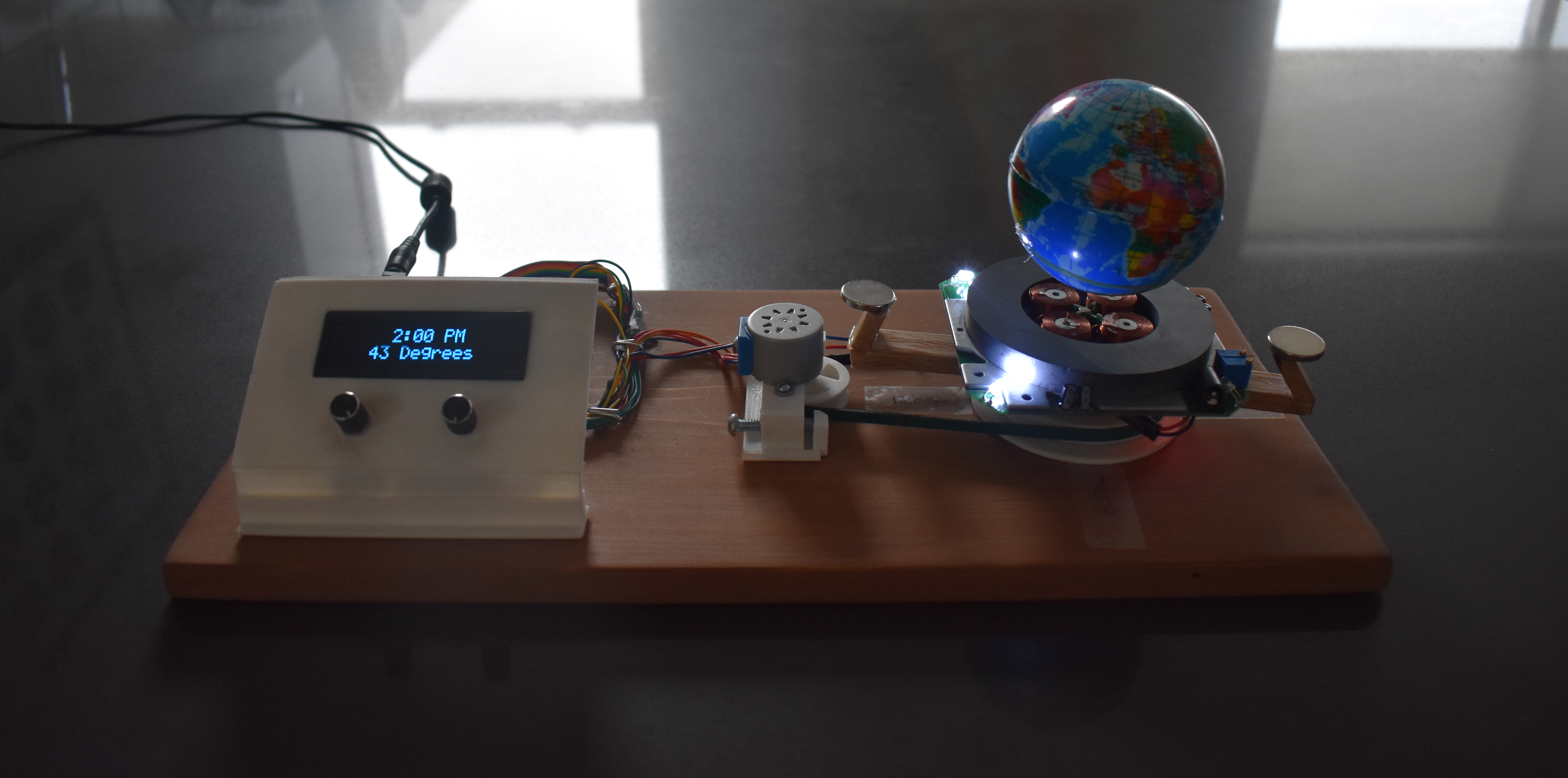
I always wanted to be able to see a live model of the Solar System. I wanted to create a physical model but not with little sticks holding up the planets like traditional orreries. To get the real feel of a ball floating in emptiness I thought it would be cool to create a model by hovering the planets with magnets while still being able to control their rotation and position. Then you could let the user choose the date and time or have a live mode where it will stay synced to the current position of the planets.
How It's Made
First attempt at hovering.
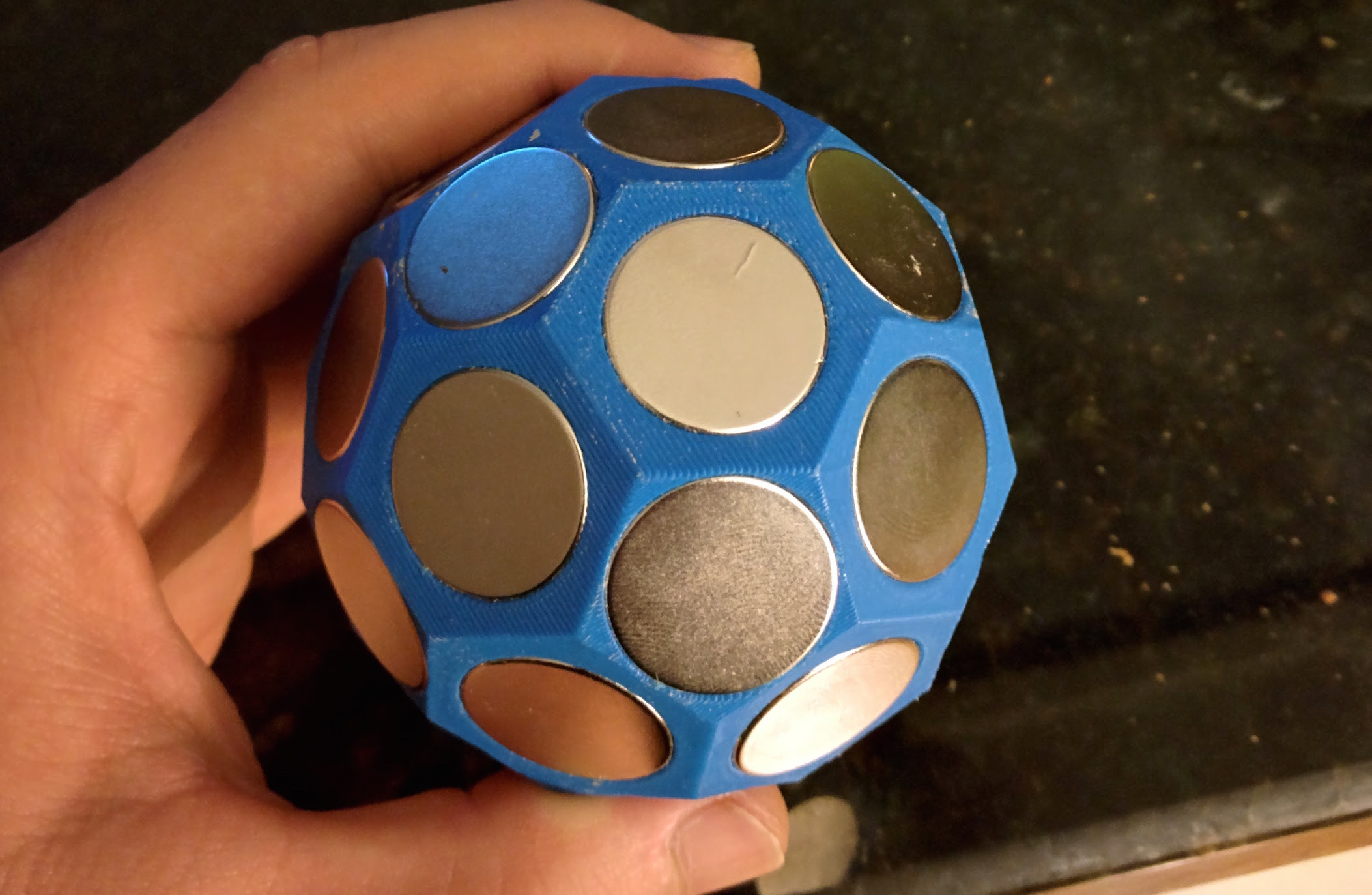
I first read that there was no such thing as stable levitation with permanent magnets but I wanted to see for myself. I bought some Neodymium magnets and 3D printed a ball and sadle that the magnets can press into. I soon knew what an unstable system felt like. Now I'm pretty convinced Earnshaw's Law is true, you can't levitate stuff with only stationary permanent magnets.
Electromagnets are the way to go.
So then I looked into magnetic levitation with electromagnets and I found a small company called Zeltom in Michigan that made a unique system for educational purposes. All of the code was open to view and learn from. I figured I could learn a lot about what it takes to levitate a permanent magnet so I bought one.
It has an impressive hover height but it's not very stable.
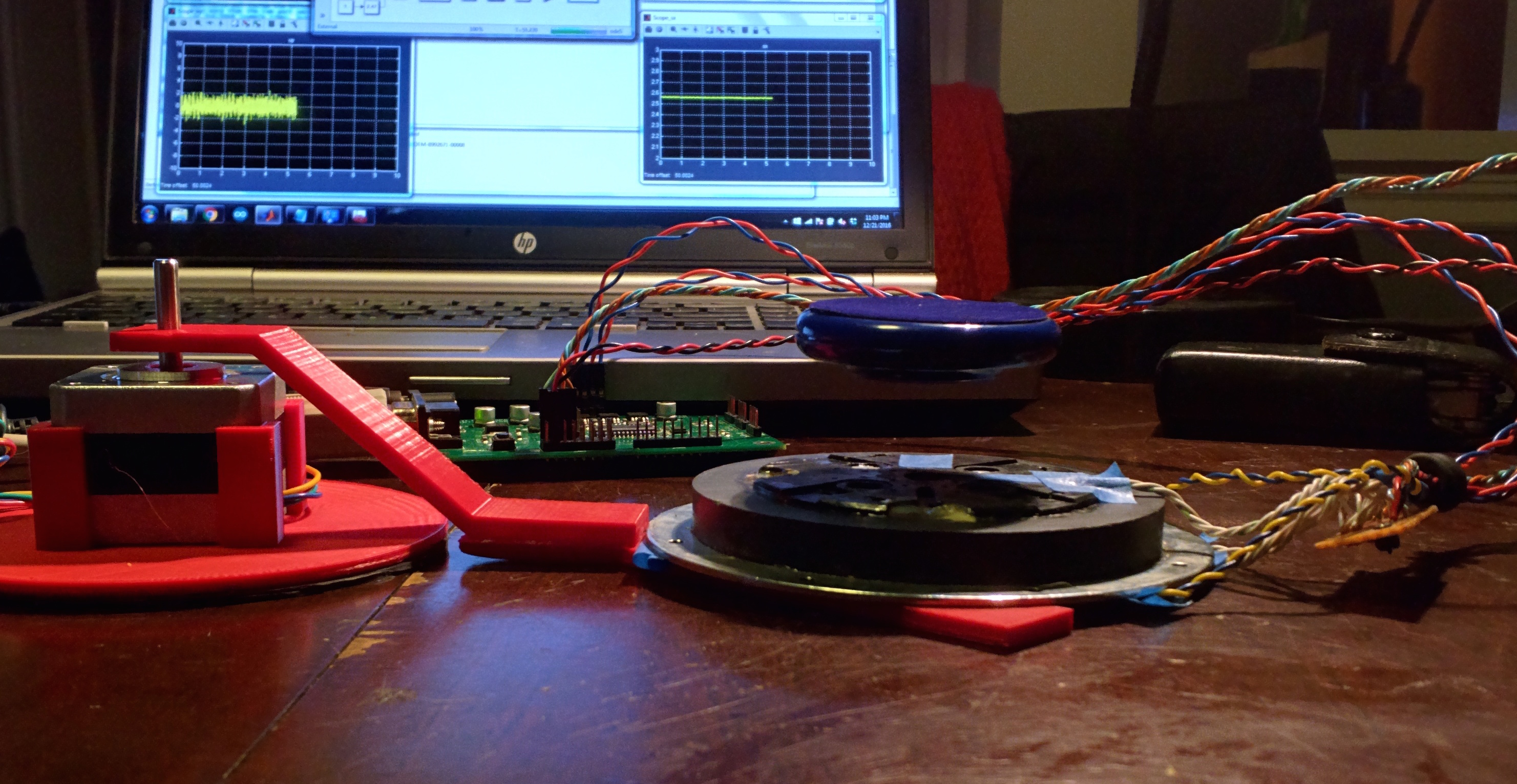
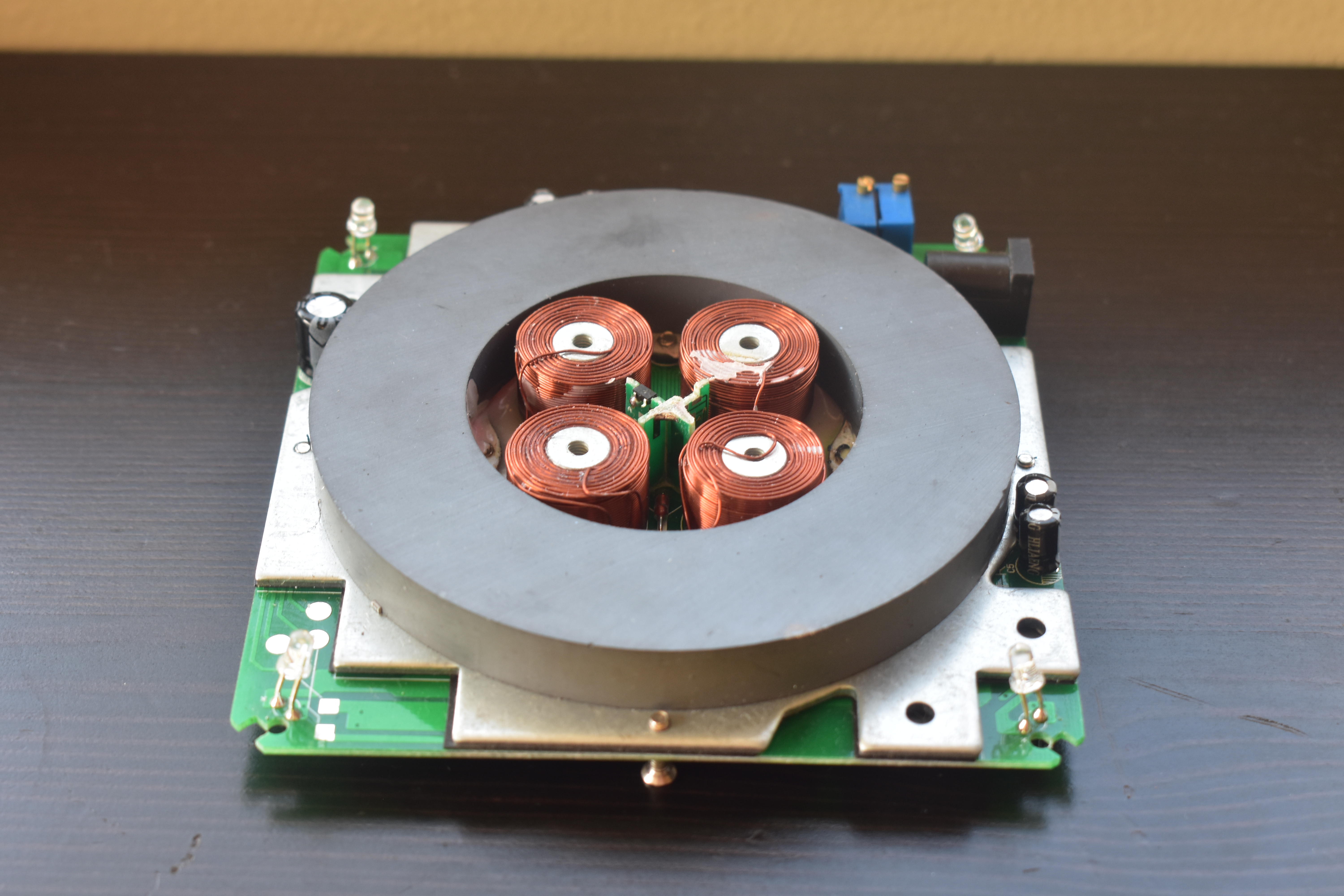
I played with this system for a while and learned about how the levitation works. Zeltom engineers were extremely helpful and willing to teach. But after looking around I found that I could buy a very stable and compact system from Amazon for $40. That was pretty good since I thought it would take me months to get my own levitation system going. So I bought one of those and moved on to the electronics.
Amazon one had a lower hover height but it was very stable.
Figuring our how to rotate a hovering planet with magnets.
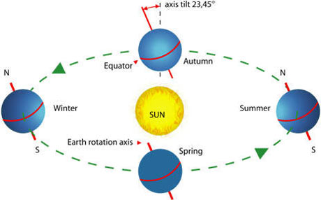
My vision was to be able to control the axis and rotation of the planets while moving them around the Sun. For the Earth, the axis is actually pretty constant at 23.5 degrees but respect to the Sun it is a rotation at 1 rev/year. That means in order to show the Earth's axis I need to rotate the tilted hovering body.
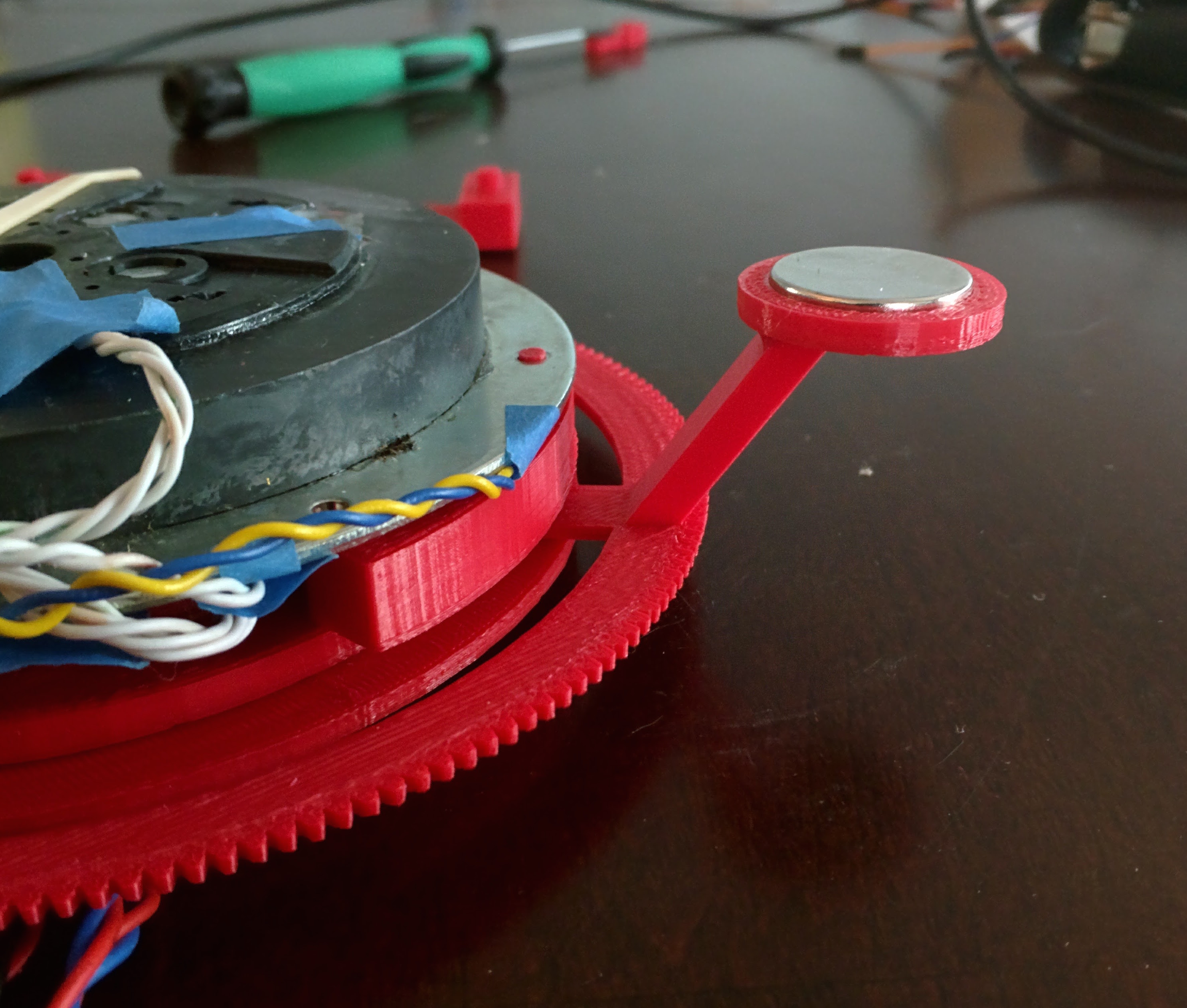
 I eventually figured out out how to rotate the hovering body after going through a number of different designs. By putting a small permanent magnet on the rotating body and then rotating another small permanent magnet of the opposite polarity at the bottom the hovering body will spin to whatever degree I want. If the magnets are small enough it doesn't effect the hovering forces at all.
Building the circuitry.
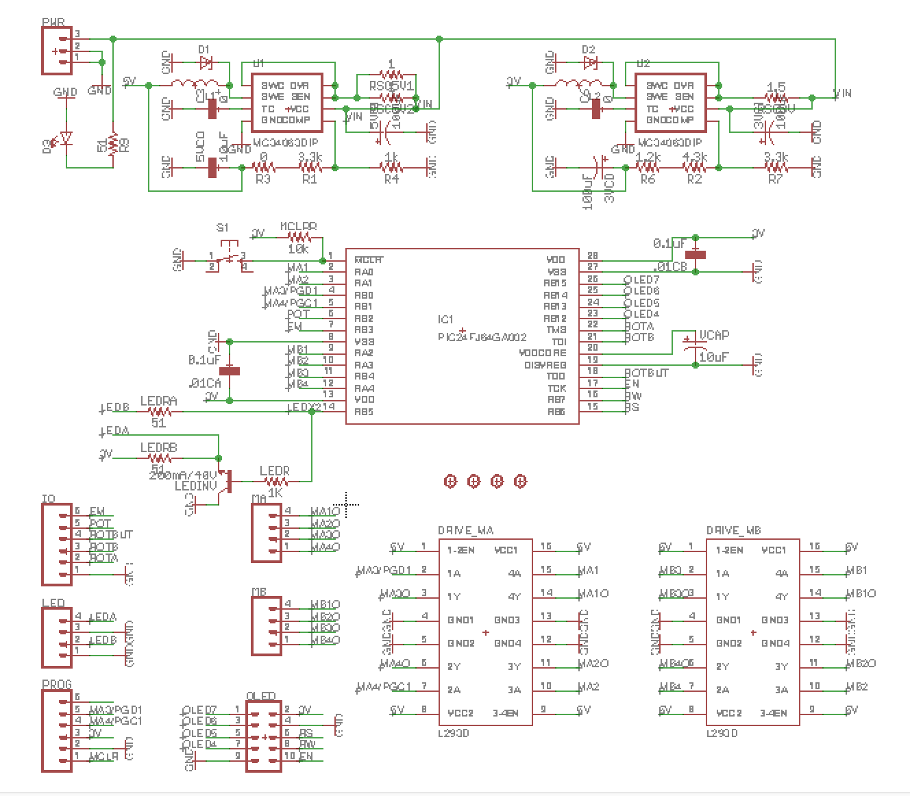
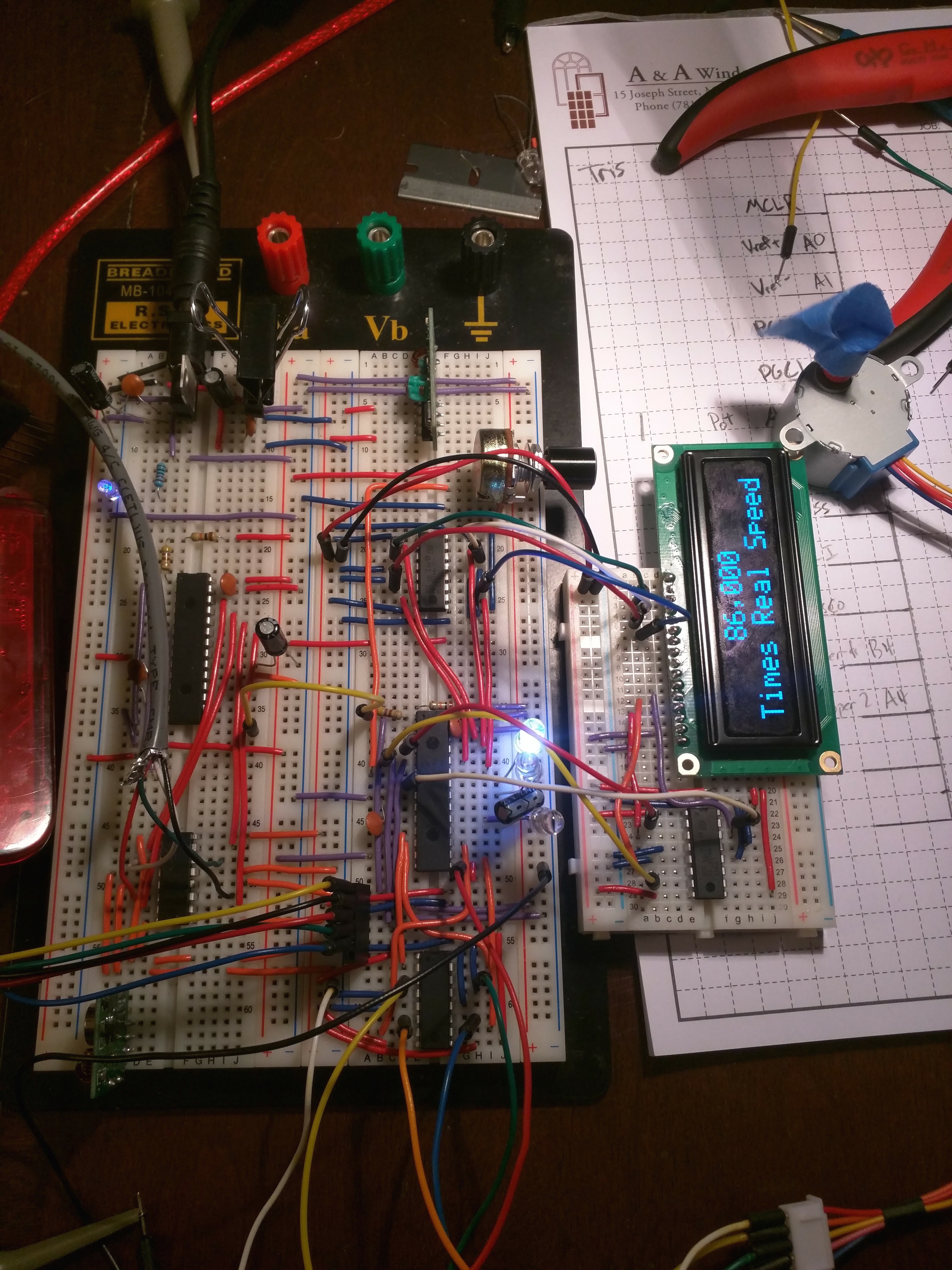
After making a small list of components I would need, I began getting a small circuit together and some code to control all of the components. I used a PIC24FJ64GA002 with some C code to control 2 stepper motors, a small OLED screen, a potentiometer and rotary encoder to choose settings, a few LEDs and 2 sensor inputs.
And then eventually got all of this working on a breadboard.
But there was just to much for the breadboard and it was very hard to move it without connections coming loose and I was also excited to get a custom circuit board printed. I used Eagle to create a small PCB design about the size of an Arduino with 2 built in stepper drivers. I had a lot of fun trying to route the board with only 2 layers and making it as compact as possible.
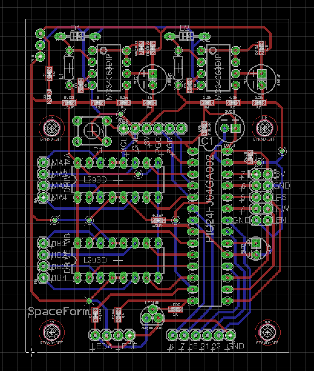
Then I got it printed by OSH Park and it turned out completely awesome.

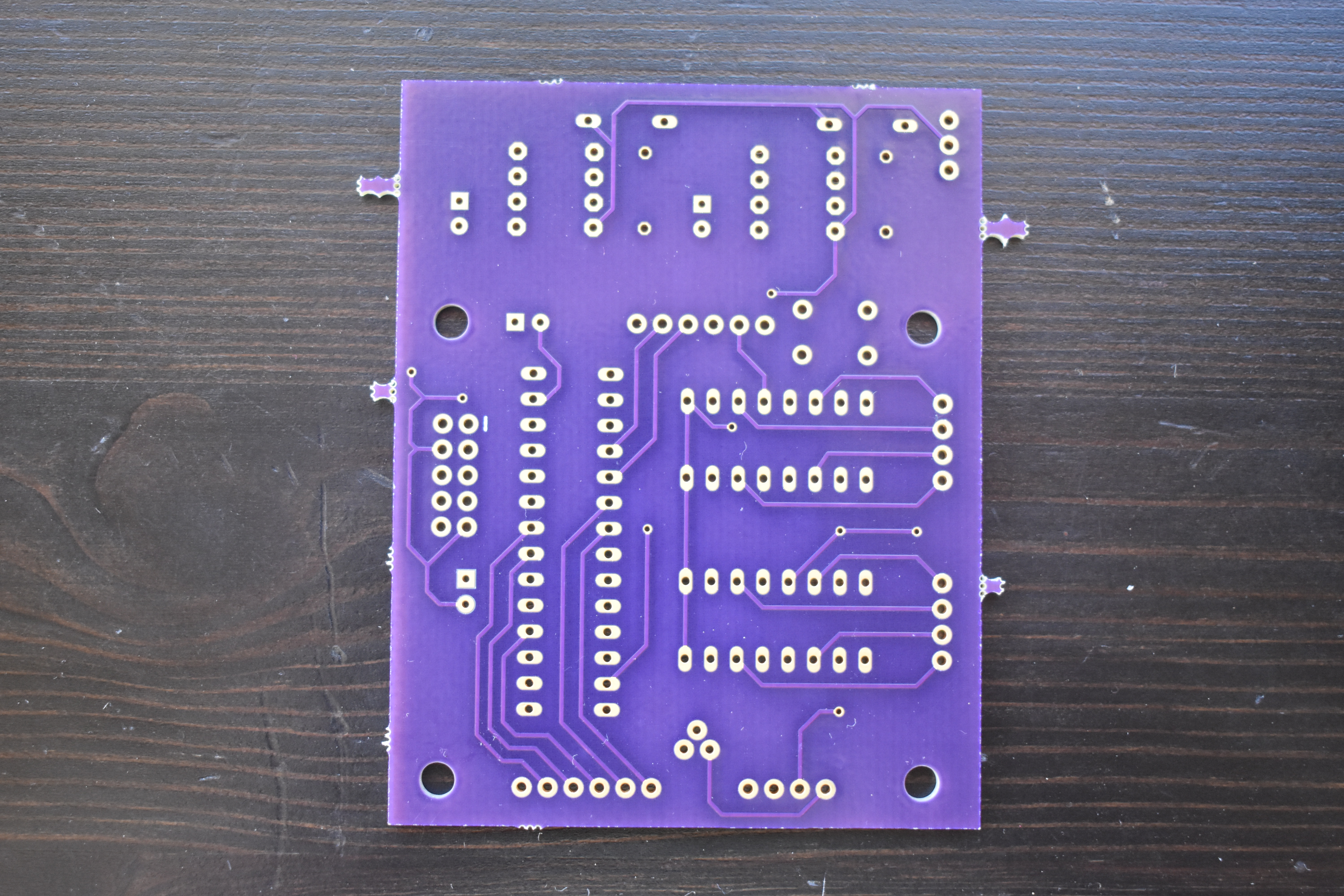
Reflow Soldering
In order to make the board as compact as possible I used a lot of surface mount components and I needed to install them by hand. I purchased a pattern from OSH Patterns so that I reflow the SMD components.
First I taped the PCB down so that it cannot slide.
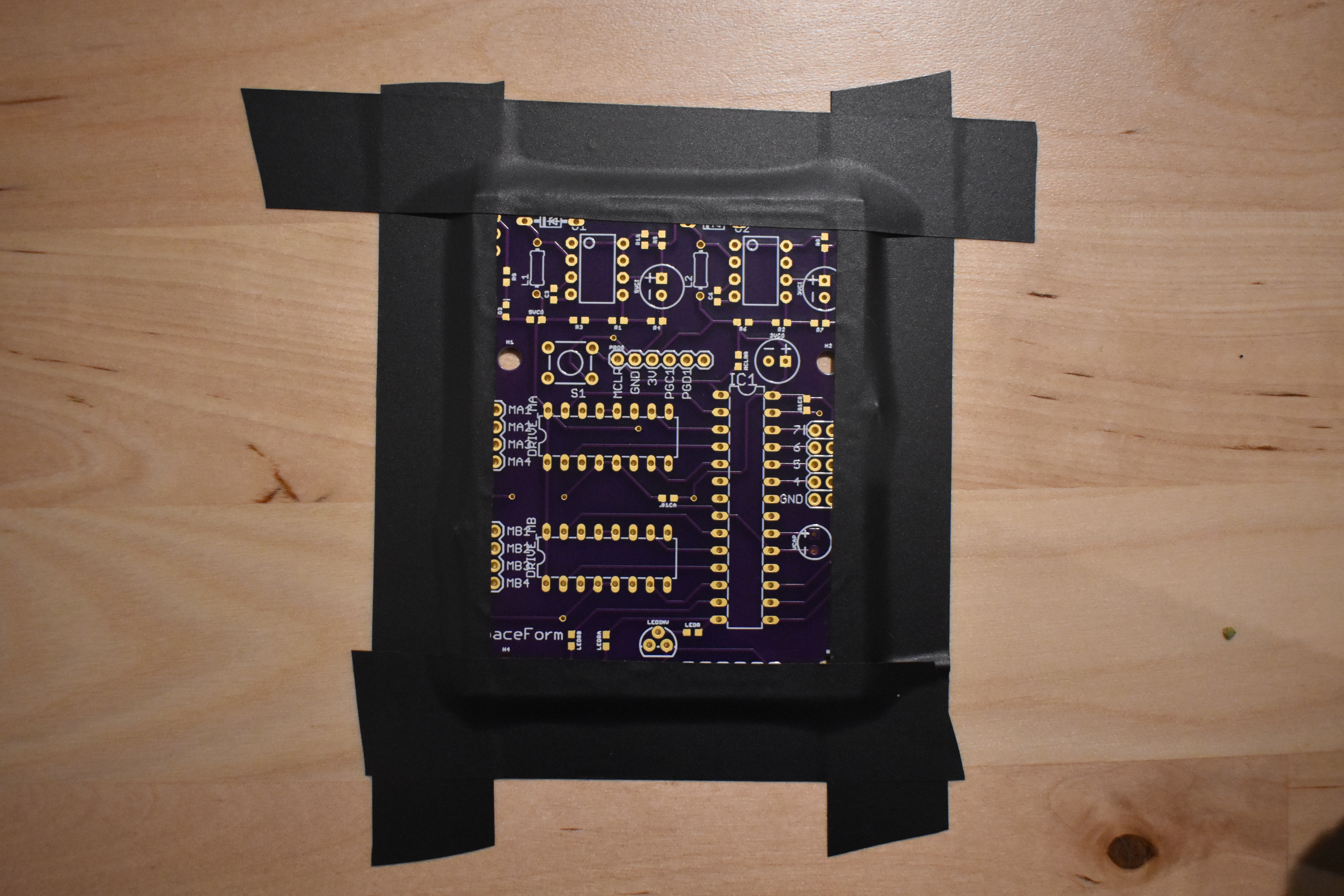
Then I taped the pattern over the board so all of the SMD pads lined up with the holes on the pattern.
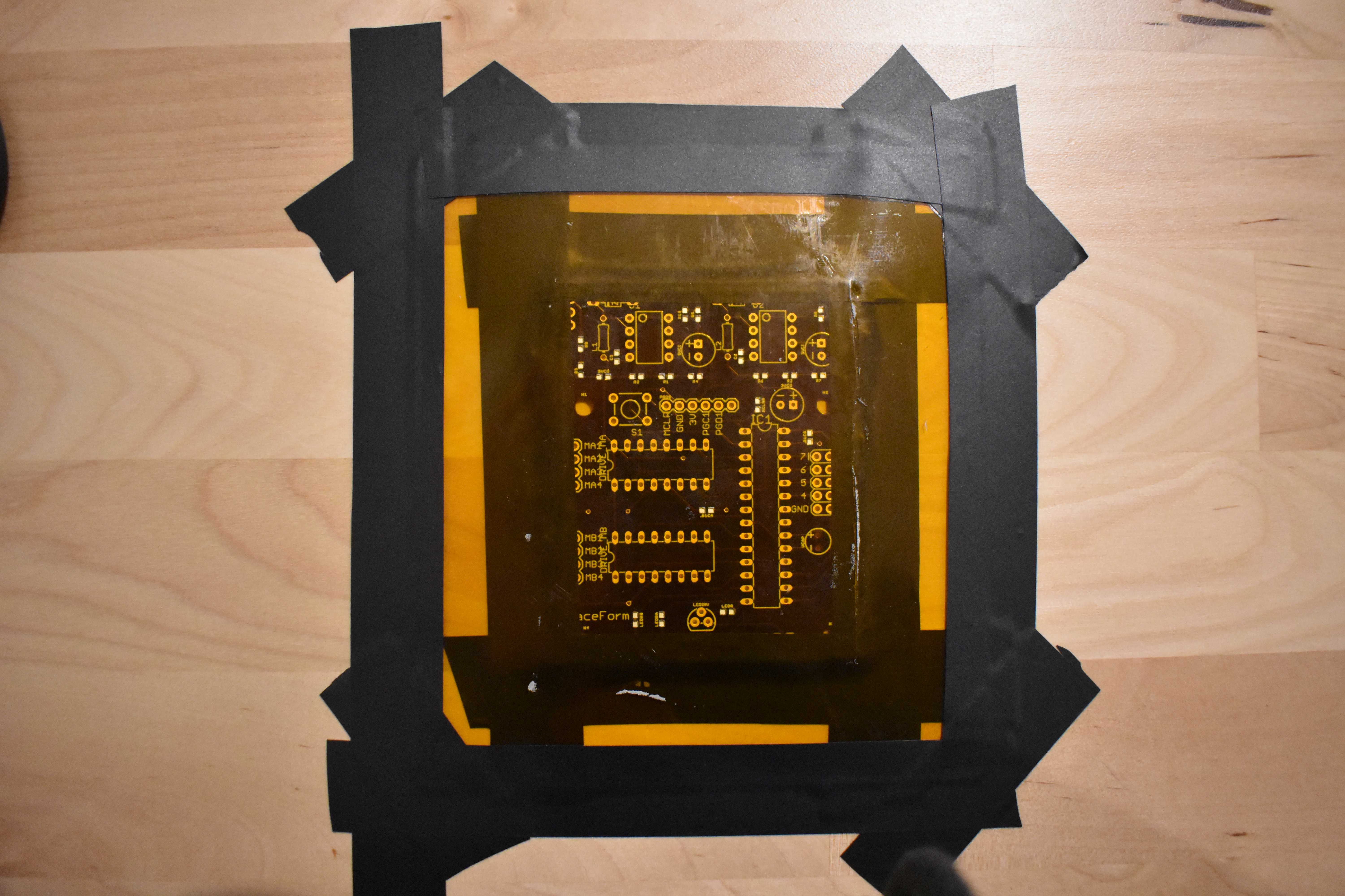
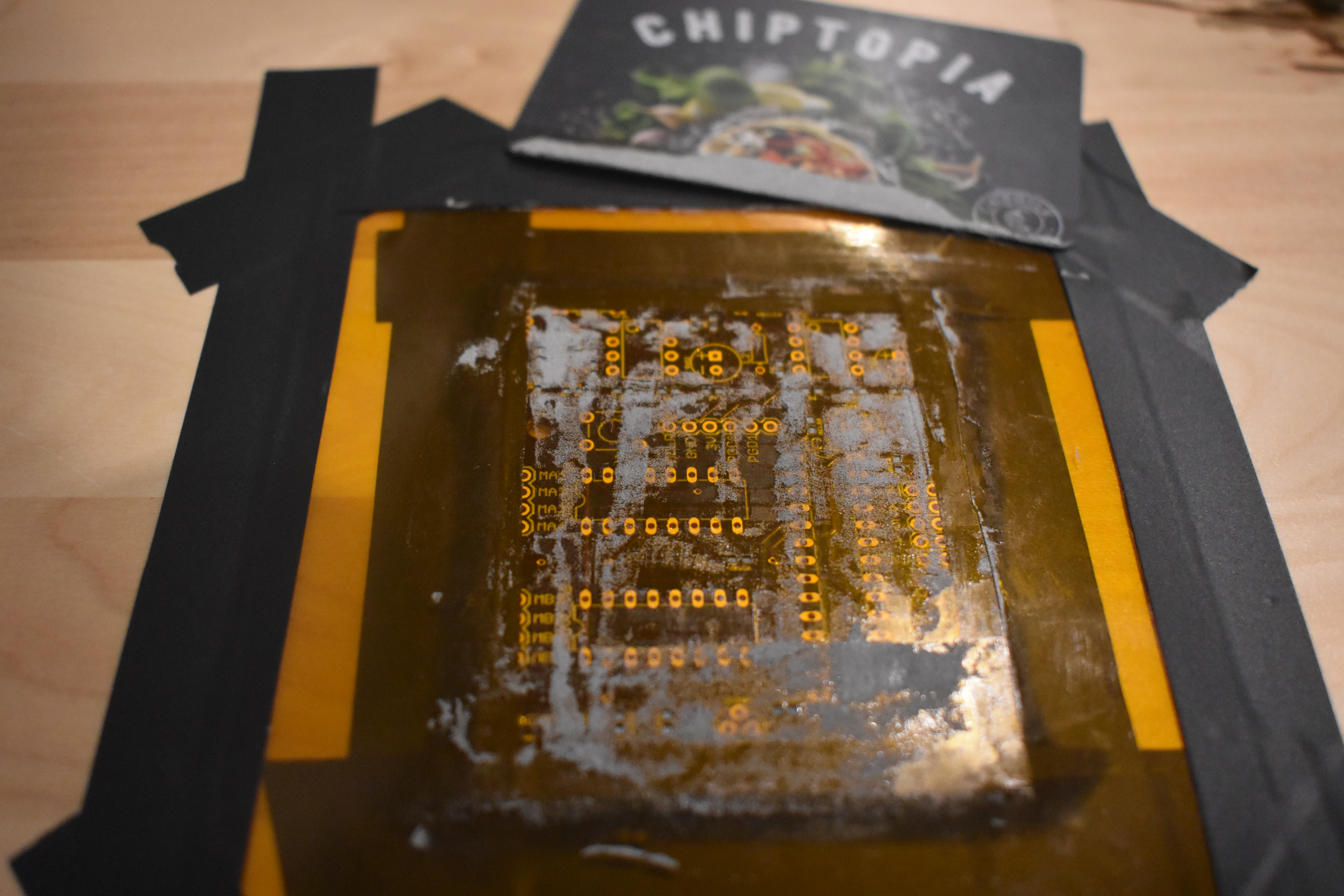
Then I spread paste on the pattern in one even swipe with a Chipotle gift card.
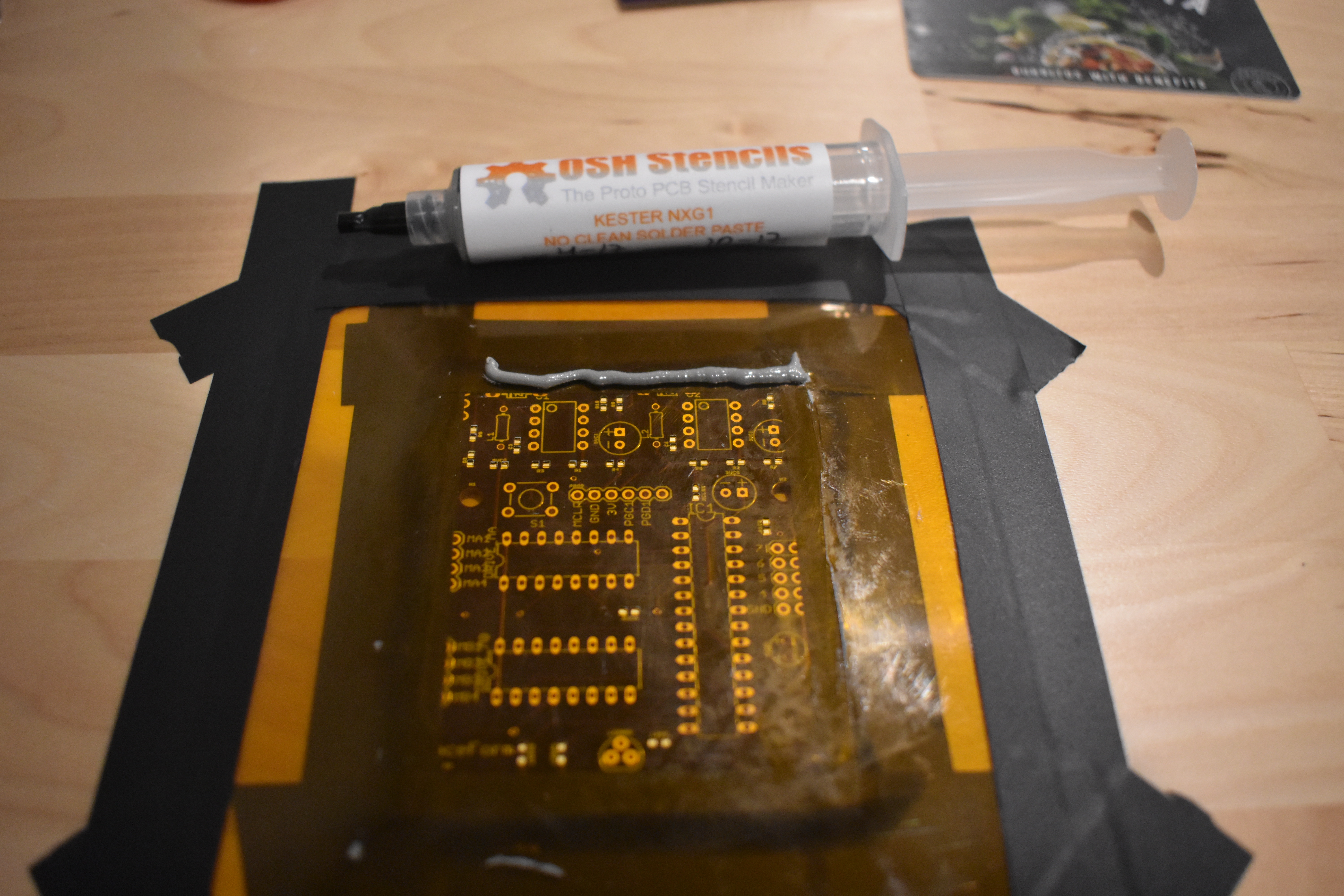
This puts an even layer of solder paste on all of the SMD pads.
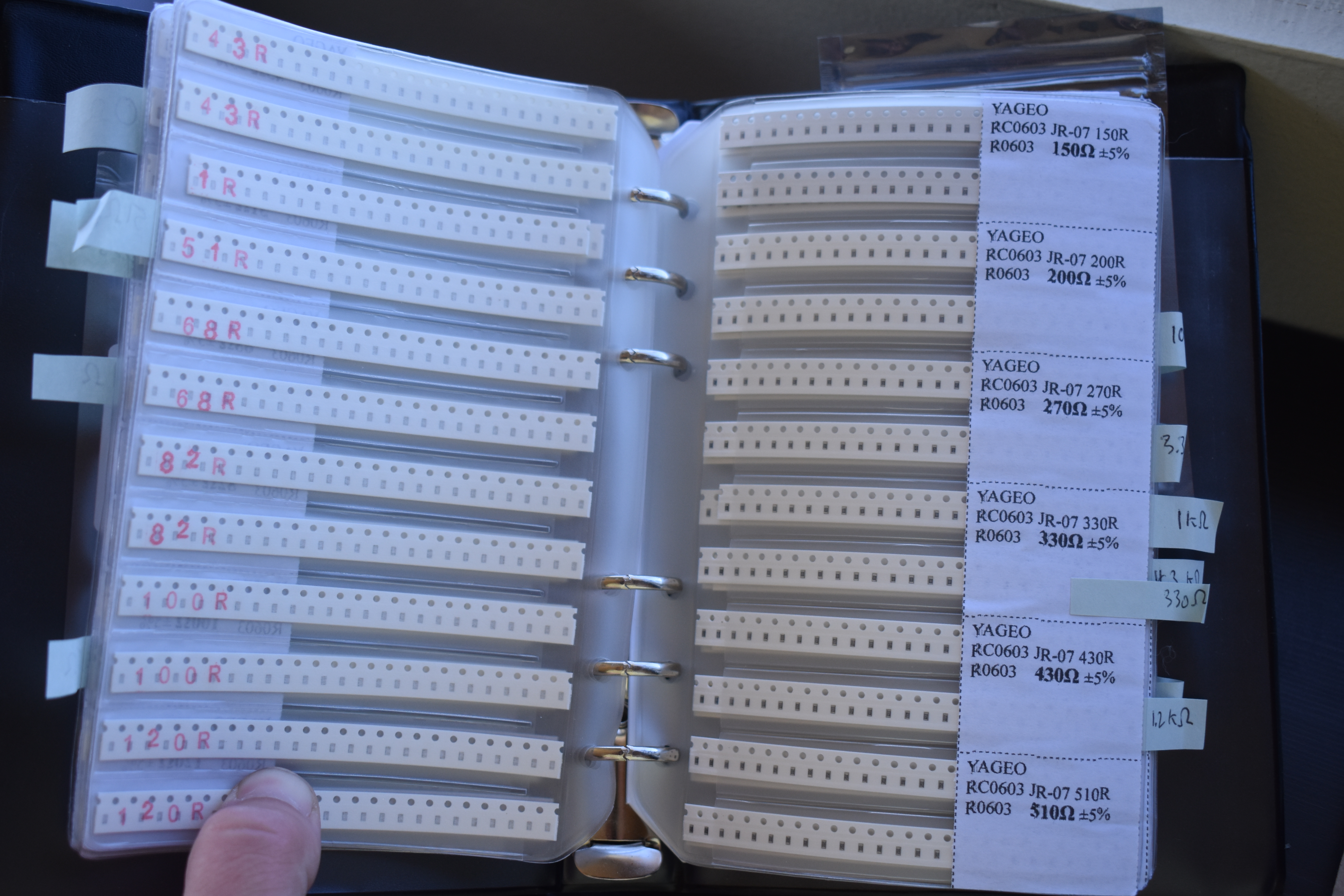
Then using a book of SMD parts I carefully placed all of the SMD components onto the board. Where they need to be
I needed about 1.5 °C per second in order to not overheat the board but I really wasn't at much risk of ruining the board because there weren't any chips on it yet. But I practiced a few times with the stove so I can get the dial just right so that the cast iron pan heated at the right speed.
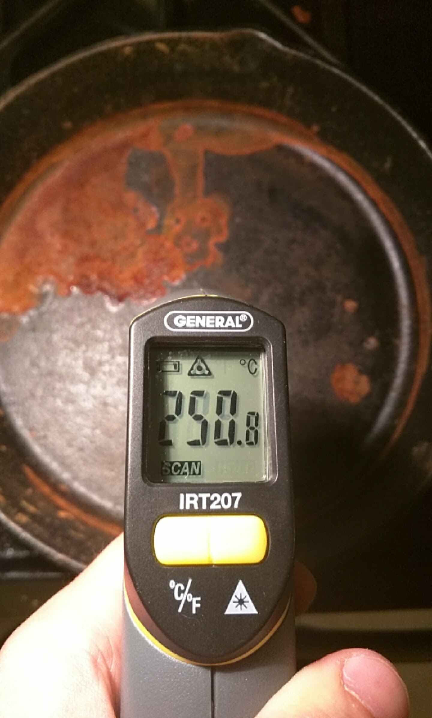
I dropped the board in and sure enough at about 250°C all the paste melted and it looked absolutely beautiful. I hand soldering the rest of the through hole components and it was ready for testing.


After some testing the board worked perfectly. Both regulators with over 20 SMD components were stable at 5V and 3V and I was able to program the PIC chip with my built in connector.
Designing the structure.
I needed a place to mount the stepper motors and a method of rotating the magnets. I first designed some gears and printed them on a 3D printer but I quickly realized that with plastic gears I would never get the quiet smooth rotation I needed. My friend, Matt Ezzi, told me to go with pullies and I never looked back.
I was lucky enough to be hooked up with some roller bearings from IKO for a pully. Then I printed some parts that the bearing can press into and rest on.


I bought some belts from McMaster Carr and printed some adjustable stepper mounts and it is as smooth as butter!

Then I needed a little control panel. So I designed an printed a small face plate with mounting points for the OLED screen and the knobs.

After a few trips to Home Depot I got a board to place all my parts on. After staining it to make it look nice, mounting all the parts with lots of hot glue and running all the wires it started to look neater.
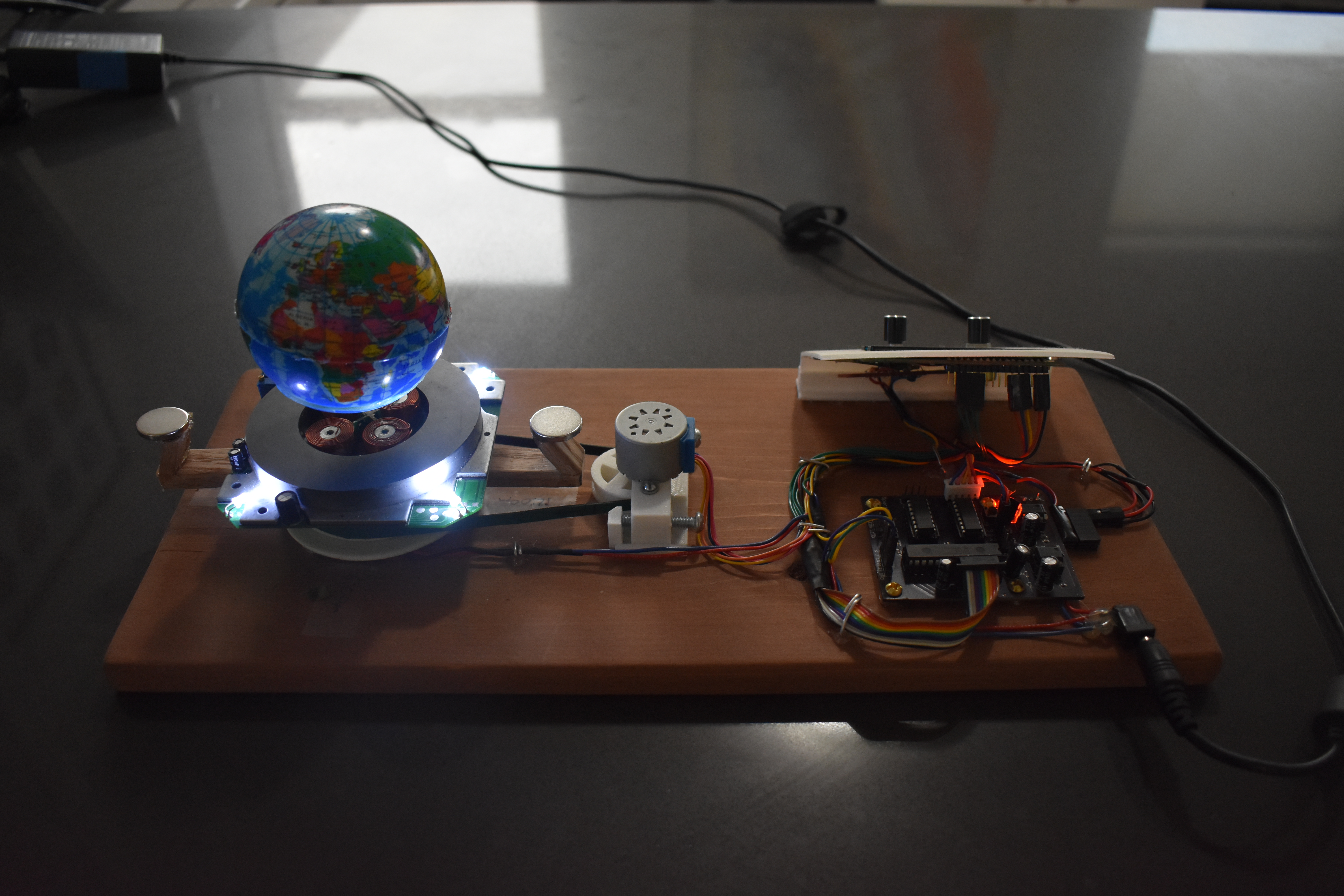
So now you can set the time and it will move the Earth to the correct position to represent that time. It also has a live mode where it will stay synced to the current rotation of Earth. Lots of room for improvement but I'm happy with the progress.

